I don’t want to spend too much time writing about the math used to analyze wind turbines because it is not very interesting for most people to read and it has already been done a million times for these 10′ turbines. I just think it will be interesting to see how these numbers will compare to the real world numbers that I get out of my turbines when they are finally flying. I’m not really a big math guy so keep me honest here if you see any mistakes.
Ok, it seems that the math for estimating the power output goes somehing like this. First you can figure out the total power available in the wind using the first formula below.
Pa = 0.5 x rho x A x V³
This is the power available to your wind turbine and is determined by the air density, size of the blades (swept area), and speed of the wind. Notice that increasing the swept area (A) and the wind speed (V³) create substantial increases in available power. You can’t change the wind density so forget about that variable (rho). Doubling the diameter of the blades (which increases the swept area according to the formula πr² ), will increase the power output by a factor of 4. Also,doubling the wind speed will increase the power output by a factor of 8. So, you can greatly increase the power output by making the blades really big and getting the wind turbine as high as possible, since the wind increases substantially with height above ground.
All the indented stuff below is taken from a discussion at https://www.awea.org/faq/windpower.html that was written by Eric Eggleston on February 5, 1998. He explains all of this by saying…
…
Power in the area swept by the wind turbine rotor:
Pa = 0.5 x rho x A x V³
Pa = power available in watts (746 watts = 1 hp) (1,000 watts = 1 kilowatt)
rho = air density (about 1.225 kg/m3 at sea level, less higher up; about 1 in Denver, Co)
A = rotor swept area, exposed to the wind (m2)
V = wind speed in meters/sec (20 mph = 9 m/s) (mph/2.24 = m/s)This yields the power in a free flowing stream of wind. Of course, it is impossible to extract all the power from the wind because some flow must be maintained through the rotor (otherwise a brick wall would be a 100% efficient wind power extractor). So, we need to include some additional terms to get a practical equation for a wind turbine.
Wind Turbine Power:
P = 0.5 x rho x A x V³ x Cp x Ng x Nb
P = power in watts (746 watts = 1 hp) (1,000 watts = 1 kilowatt)
rho = air density (about 1.225 kg/m3 at sea level, less higher up)
A = rotor swept area, exposed to the wind (m2)
V = wind speed in meters/sec (20 mph = 9 m/s)
Cp = Coefficient of performance (.59 {Betz limit} is the maximum thoretically possible, .35 for a good design)
Ng = generator efficiency (50% for car alternator, 80% or possibly more for a permanent magnet generator or grid-connected induction generator)
Nb = gearbox/bearings efficiency (depends, could be as high as 95% if good)
…
Notice from the equations above (the Cp or Coefficient of performance variable) where he says the maximum power that a wind turbine can theoretically generate is ~59% of what is available in the wind. This value is called the Betz limit and was discovered in 1919. Above this value the wind appearently backs up in front of the blades or goes around them and just can’t be converted into power. This is basically the efficiency limit of the wind turbine blades. Appearently, most well done homebrew wind turbines are doing very well if they to approach a 30% Cp, unlike some commercial turbines, which are getting much closer to the Betz limit (I’m not sure how close to 59% they are getting).
So from this discussion we are now able to figure out roughly what our power output will be if we build everything right on this wind turbine. It is important to point out though that you have to make sure to account for the loss of efficiency in the bearings and alternator, as well as the blades, which is where Cp, Ng, and Nb come from. From what I have read, it seems that the blades, bearings, and alternator all need to be very efficient to get even 30% overall efficiency and this is about where people say these 10′ homebrew wind turbines tend to run. The numbers I have used in the formulas below give it about 30% overall efficiency for this reason. I don’t really know exactly how efficient these individual values are in reality, but I think these are close. So the numbers for this wind turbine would look something like this…
P = power in watts
rho = 1.05 (density of air around denver, co)
A = 10 foot diameter (which equals 9.57 meters squared)
V = 10 miles per hour ( which is 4.47 meters per second)
Cp = 40% (so we have a very efficient rotor)
Ng = 80% (since we are using good quality bearings)
Nb = 95% (since we have a very efficient direct drive alternator)
P = 0.5 x rho x A x V³ x Cp x Ng x Nb
P = 1/2 x 1.05 x 9.57 x (4.47)³ x 0.40 x 0.80 X 0.95 = 136.41136.41 (watts in 10 mile/hour wind)
P = 1/2 x 1.05 x 9.57 x (6.71)³ x 0.40 x 0.80 X 0.95 = 461.44461.43 (watts in 15 mile/hour wind)
P = 1/2 x 1.05 x 9.57 x (8.94)³ x 0.40 x 0.80 X 0.95 = 1091.331091.33 (watts in 20 mile/hour wind)
Another helpful equation is one that helps you calculate the RPMs of your wind turbine at a given wind speed. You must be able to calculate RPMs over a range of wind speeds in order to build the alternator appropriately, so this is very important. The tip speed ratio (TSR) in the equation below is simply the ratio of the speed that the tip of the wind turbine blade is travelling divided by the wind speed.
Revolutions / Minute (RPM) = V x TSR x 60 / (6.28 x R)
V = Wind speed (m/s)
TSR = Tip Speed Ratio
R = Radius of rotor (meters)
So, for the 10′ turbines we will have…
V = Lets us 10 miles per hour, which is 4.47 meters per second
TSR = 6
R = We have 5 foot radius which is 1.52 meters
RPM = 4.47 x 6 x 60 / (6.28 x 1.52) = 168.58 (in 10 mile/hour wind)
RPM = 6.71 x 6 x 60 / (6.28 x 1.52) = 253.06 (in 15 mile/hour wind)
RPM = 8.94 x 6 x 60 / (6.28 x 1.52) = 337.16 (in 20 mile/hour wind)
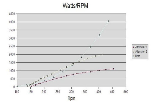
Now you can compare these numbers to the real world power curve from the otherpower.com folks below. I believe this graph was produced from a real world test of their alternator performance, probably mounting it to a drill press or something. “Alternator 1″ below is the same alternator that I have built for these two turbines (using 2 x 1 x 1/2 inch magnets, 12” disks, and 140 turns of 17 gauge wire). Comparing the numbers we computed above, you can see that the numbers are a bit different but not too badly off. This approach would give us numbers within the relm of what the wind turbine will produce. I think the values drop off in this real world test primarily because the alternator becomes less efficient at higher RPMs. I guess you loose more power to friction in the bearings as well. Anyway, that is enough math…building the turbines is much more fun…