Assembling the Blades

The blades arrived a couple of days ago. They only cost about $80 dollars + shipping. I think that is quite a good deal. They are not the highest quality but look pretty good for cheap blades from China. They are definitely much heavier than the cedar blades we carved last year at the sustainable living festival. I think they need to be coated with something to protect them from UV radiation as well.

Anyway, I built a couple of 12 inch wood disks to hold the blades together from the front and back. The back disk needed a 2 3/4 inch hole so it can slip over the hub and spindle. It needed 9 bolts (3/8 x 4 inches) to hold the blades to the disks. I think the roots on these blades are too small and the bolt holes too close together…I’m not sure how strong this could be in this arrangement. I guess we will see when it is flying.

After getting it all put together I measured it at about 9 1/2 foot diameter…so it is a bit smaller than the 10 foot diameter plans. This will definitely affect the power output since the power is related to the swept area of the blades. These blades have a higher tip speed ratio (TSR or 8 instead of ~6) because they are a more efficient airfoil. I will need to think a bit more about this but I think this higher TSR might cancel out the affect of a smaller swept area (and higher RPMs). I’ll have to make a posting on www.field lines.com and run this by the experts. I might be able to do a little math and figure this out too. Again, I can always reduce the efficiency of the alternator by making the air gap larger so it does not stall out at a low cutin speed (I think). Here are some pictures…

iphone-7-10-2009-8-32-24-am iphone-7-10-2009-8-33-01-am iphone-7-10-2009-8-33-21-am

Testing the Alternator

So it is time to test out the alternator. This is the moment of truth because it determines how well I have done on all the other steps up until this point. In fact the wind turbine is really mostly done. Sure there is a lot to do to get the electrical system working and erect it on a tower, but the turbine itself is pretty much done.
The Homebrew Wind book has a number of suggestions for testing it out. You can do a couple of quick and dirty tests like shorting out the leads and making sure the alternator is reacts correctly. The alternator should get “lumpy” to turn when two leads are shorted. It should be smooth but difficult to turn when all three AC leads are shorted. This guy passed those test for sure, so I don’t think there are any obvious problems with the coils.
I bought a full bridge rectifier the other day off of ebay that should work for converting the alternating current coming out of the turbine into direct current. It only cost $10 so I thought I’d try it out. It is rated for 55 amps but I’m not sure what kind of voltage it can handle. I bet it will work since it was built specifically for this type and size of wind turbine. This turbine should only produce about 35 amps at peak output, so I think it will work. Here it is below…


iphone-7-10-2009-8-31-33-am iphone-7-10-2009-8-31-57-am


So it appeared to work fine once it was hooked up.
iphone-7-10-2009-8-32-11-am
The DC leads are a bit strange on this rectifier. There aren’t any screws so I will need to tap the holes on it at some point. Anyway, at this point I wanted to do a little more testing like the Homebrew Wind Power book calls for. It says this turbine is supposed to have a cutin speed (lowest speed at which it produces the rated voltage of 48 volts) of about 140 RPMs. They say it can be within 20 or so RPMs in either direction. I don’t have a laser tachometer yet so I estimated the RPMs at 48 volts a couple of times and it looks like this alternator is producing 48 volts at roughly 135 RPMs !!! I will check it again when my tachometer arrives, but I think we are good.


I haven’t testing amperage at all but it seems to be creating quite abit of power. I hooking a 12 volt motor to the DC leads and just by hand cranking the alternator the motor starts to scream!! I can’t wait to do a power curve of this thing. I really want to see a curve of wind speed, RPMs, voltage, and amperage. I’ll need to figure out a good way to get all this information without having a wind tunnel to test it.
iphone-7-10-2009-8-34-22-am iphone-7-10-2009-8-35-08-am
I ordered some fiberglass (WindMax 9.2 foot) blades the other day because I am not sure whether I am going to carve the specified wood blades for this turbine or not. I need to think a bit more about how these smaller blades are going to affect the performance. I bought slightly smaller blades because I think it is better to have a over powering alternator as apposed to a overpowering set of blades. the air gap between the magnet rotors can always be widened to produce a bit less inductance if I need to match the alternator to the blades. This is a bit of a waste of magnets and copper but it is tough I guess to match things perfectly, so whatever…

Assembling the Alternator

I forgot to take pictures of the assembling process so here is the atlernator fully assembled. It worked out pretty well. The stator coils are slightly offset like I thought, but not too bad. I will drill new holes next time it is disassebled in order to get the coils perfectly aligned over the magnets. It definitely is producing electricity judging from the sparks you get from turning it by hand and cancelling out the leads.
It was a bit more work than I thought to put it together. You have to be really careful so you don’t loose a finger between your wrench and the magnet rotors……ooooch these things bite hard!! You simply have to use jacking screws in order to bring the second magnet rotor down onto the machine. It is unbeleivable the kind of force these magnets can create. There is at least a couple hundred pounds of force between the opposing rotors so you can’t lower it by hand.
iphone-6-29-2009-8-30-15-am iphone-6-29-2009-8-30-43-am iphone-6-29-2009-8-31-05-am iphone-6-29-2009-8-31-15-am iphone-6-29-2009-8-31-39-am

Building the Stator Cont.

Time to fix up the stator. It had a bunch of air bubbles in it, so I taped up the edges and poured a bit more resin to fill them up. That worked really well as you can see from the images below. It still looks a bit patchy but it should work fine…regardless of how ugly it is.
iphone-6-25-2009-10-15-51-pm iphone-6-25-2009-10-15-57-pm iphone-6-25-2009-10-16-06-pm
Next I drilled the 1/2 inch holes for the stator bracket so the stator can be hung on the alternator, and I drilled the 1/4 inch holes for the brass terminals lugs that you see below. Each of the terminal lugs corresponds to one of the phases in the 3 phase alternator and produces AC current slightly out-of-sink with the other two phases.
iphone-6-27-2009-12-48-02-pm iphone-6-27-2009-12-50-19-pm
You can’t really tell from the pictures but it turns out the copper coils were put into the mold just about a 1/8 inch to far to one side. This may cause a slight problem when mounting the stator later. I think it will be ok though. I may need to redrill the mounting holes or bend the stator bracket a little in order to fine tune it. We will have to see once it is assembled. I will not make this mistake on the next one for sure.
iphone-6-29-2009-8-31-15-am
Anyway, the stator is done. This is definitely the most challenging part of building the wind turbine. A lot of things can go wrong and it can cost you a bit of money, so take your time and do it right. I think the coils being slightly offset is the first thing that I have done wrong so far and I hope it turns out not to be a big deal. We will see.

Building the Stator

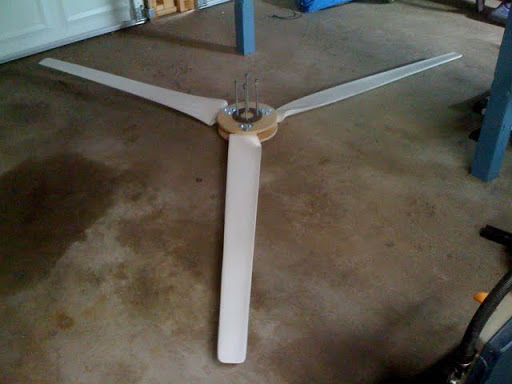
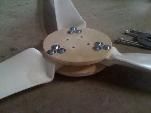
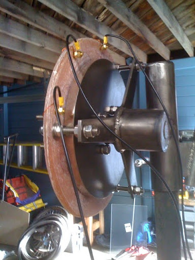
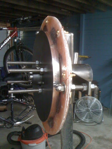
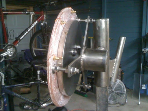
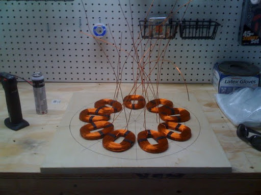
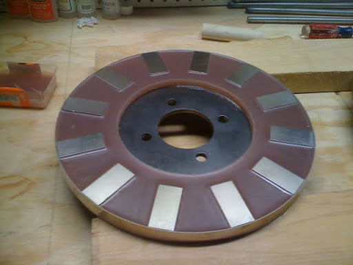
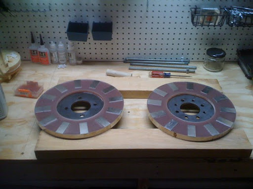
I started building the stator the other day. This the stationary part of the alternator that sits between the spinning magnets and actually induces the electric current. It is what they call a 3 phase radial axis alternator and it has 9 copper coils and 12 magnetic poles. Of course, we have built two magnet rotors with 12 magnets each, one for each side of the stator. So it is a 12 pole alternator but it has a total of 24 magnets. The interesting thing about using magnets on both sides of the stator like this is that it increases the magnetic flux by a factor of 4. So it is a very good use of magnet material because you get 4 times the electrical output for twice the magnetic material.
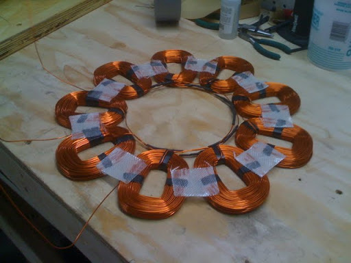
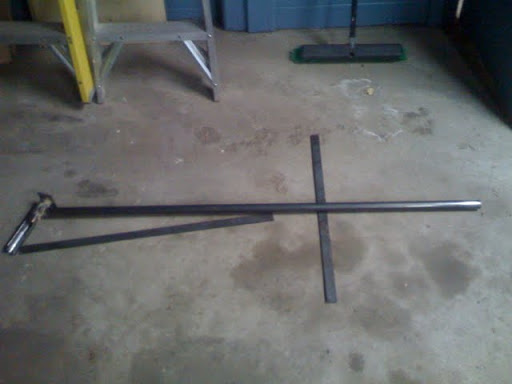
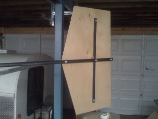
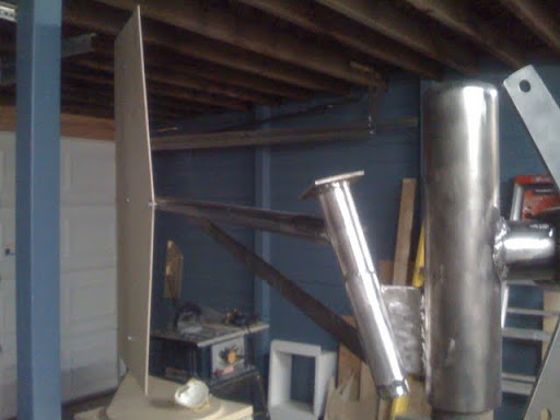
Building the stator has been the trickiest part of building the entire wind turbine so far. You have to be very careful or a number of things can go wrong. Basically, you are making 9 copper coils (3 for phase 1, 3 for phase 2, and 3 for phase 3), wiring them in a star configuration, and then casting them into a do nut shape using vinyl ester resin. The stator will then look like a thin disk of copper coils that will be sandwiched between the magnet rotors. The do nut hole exists in the stator so it can slip over and attach to the frame that was built earlier.

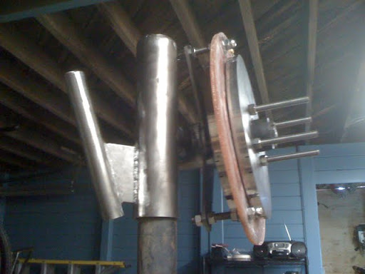
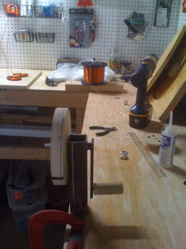
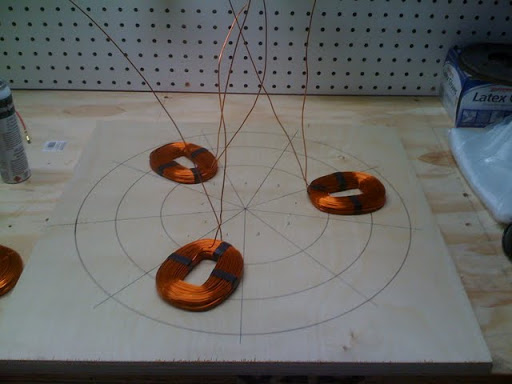
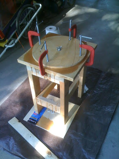
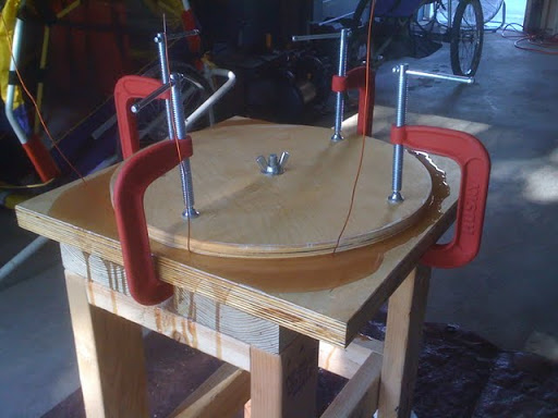
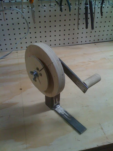
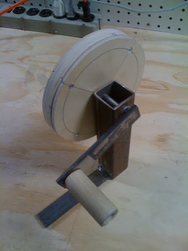
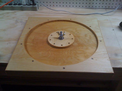
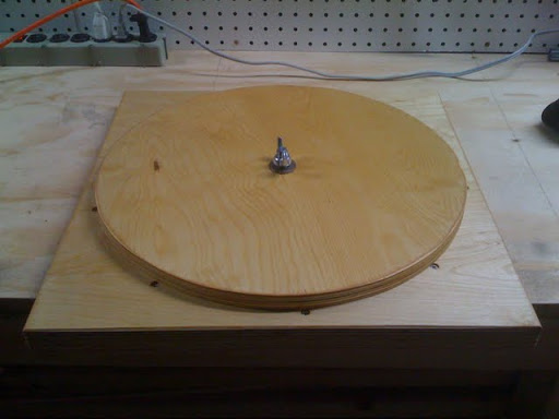
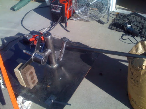
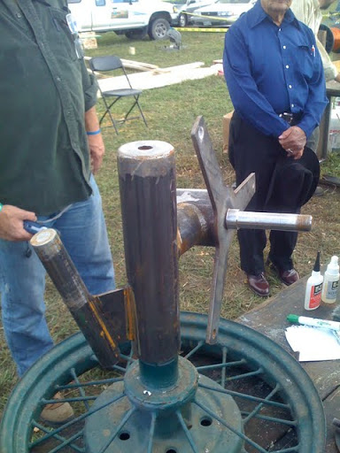
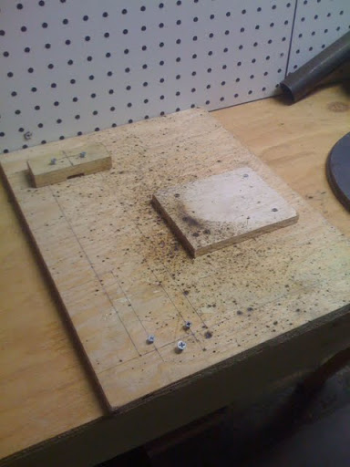
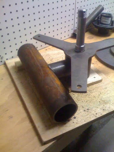
I wound the coils using my home made coil winder that you can see below. The Otherpower book had plans for the coil winder too.

iphone-6-6-2009-2-59-52-pm

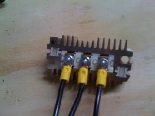
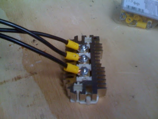
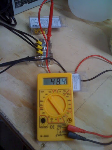
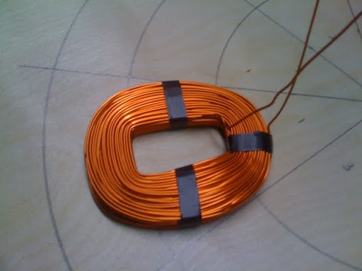
I then spent a lot of time soldering and heat shrinking everything together. It is difficult to get the coils spaced properly and all the leads soldered correctly and keep everything tidy. You have very little space to work in and are worried about shorting out a coil from all the bending and such. I didn’t do a voltage drop or resistance test or anything like that to test the finished copper windings so hopefully everything was done right. I won’t know until I put the alternator together. Take a look at the copper windings pics below. Oh, and thanks Jay for all your help with winding and soldering the coils. I bet you thought you would never see the day that I actually cast them in resin.

iphone-6-6-2009-2-59-29-pm iphone-6-6-2009-2-59-35-pm iphone-6-6-2009-3-00-20-pm iphone-6-13-2009-1-25-31-pm

It would be nice to build the alternator with the leads of the coils pointing towards the outer diameter of the mold so you didn’t have to risk any bad solders that are then encapsulated in resin. If you make one mistake you have ruined the entire stator at a cost of about $100 or so. I might try this alternative arrangement instead on the next one.

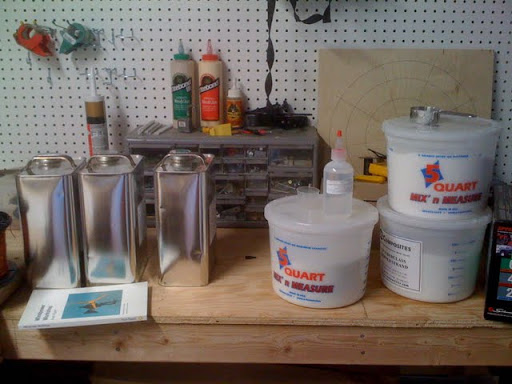
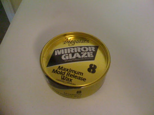
Next I waxed the mold and got all the resin ingredients together and measured out…

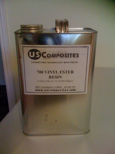
– 1 and 1/2 quarts of vinyl ester resin.
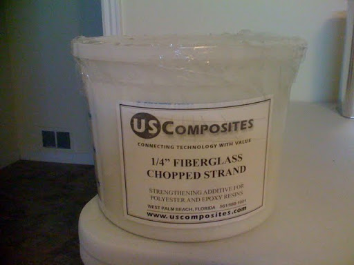
– 1/4 pint of fiberglass strand (1/4 inch long)
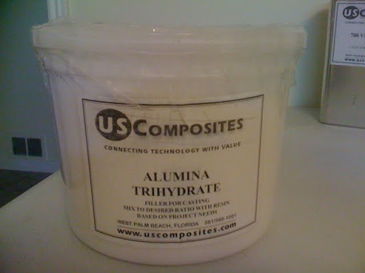
– 3/4 pint of ATH filler
– 1/4 ounce hardener

iphone-6-21-2009-5-39-59-pm

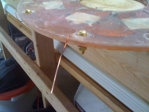
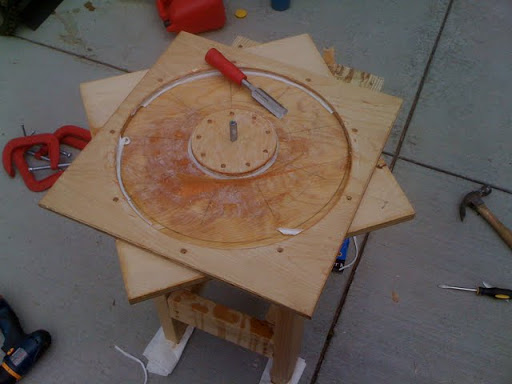
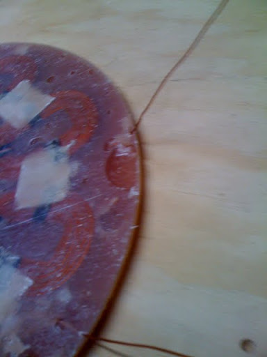
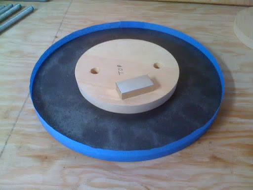
I decided to use the amounts above for a few reasons. I did not use as much filler as the book recommended because I wanted the mix to be less viscous so I didn’t have to worry about air bubbles being trapped in the mold. I also added a little fiberglass to add strength. I used a bit more hardener on this cast then with the rotors because it just didn’t seem to set without adding heat last time. Hopefully it will set in a reasonable amount of time. At this point it has been like 5 hours and it has not really hardened up much if at all. I’m going to let it sit over night and see what happens. If it looks the same in the morning then I am going to apply heat using an electric space heater. Anyway, here are a couple of pictures of it sitting in my garage. Notice the three copper leads sticking out of the mold.

iphone-6-21-2009-5-39-30-pm iphone-6-21-2009-5-39-37-pm

Well the mold did NOT appear to harden up much at all over night. I was not too concerned though because I knew from my experience with the rotors that I could just apply a bunch of heat in order get it to fire off. So, I let it set all day in the garage. It got up to around 95 degrees and then started to cure really well. It is about 7:00 in the evening now and it looks like it is well on its way to setting up. I’m going to wait a good while longer thought to make damn sure I don’t ruin the cast by opening it too early. I hope it turns out nice…or I’ll be a bit disappointed.

Well all’s well that end well. I ended up waiting another day before opening the mold. I took a bit of advice from the forums…

https://www.fieldlines.com/story/2009/6/22/32158/2446

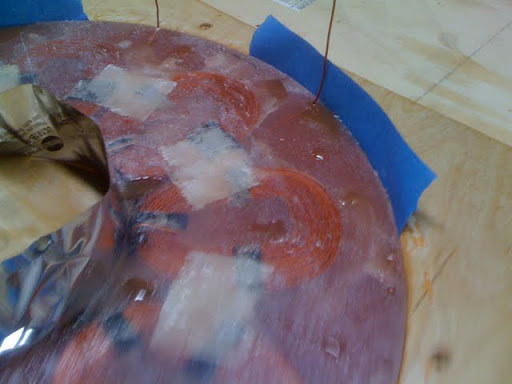
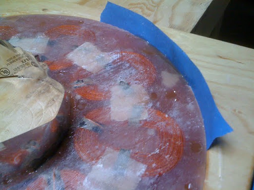
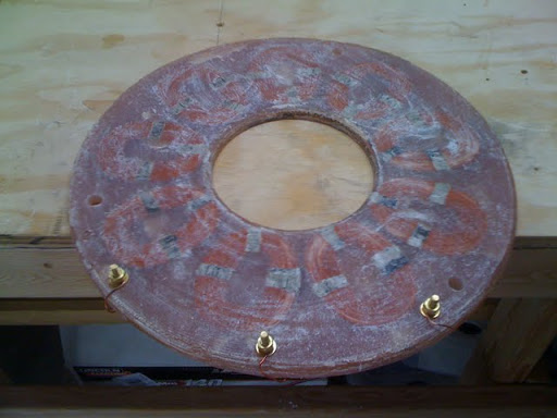
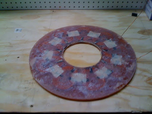
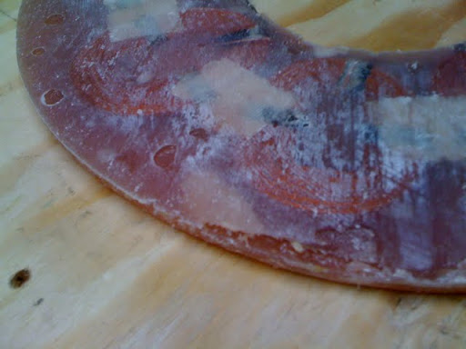
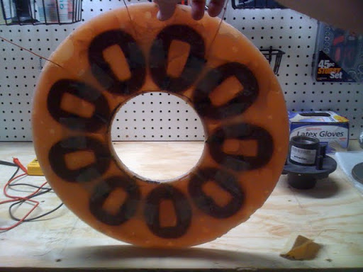
After a couple hours in the sun the mold (and my tester) was totally cured. I guess UV does work. Well my temperature gauge registered 107 degrees on the mold too, so that had a lot to do with it. Anyway, it cured up nicely even with so little hardener (about 1/2 %) but it did take some heat. I don’t think it would have ever cured without it. Unfortunately, there were a number of air bubbles but they all look like they are cosmetic and fixable. I am going to use a bit of tape around the edges and pour more vinyl ester resin into the hollow spots…maybe put something flat on top to smooth it out.

The mold was destroyed in the process of removing the casting. The bottom of the mold even pulled up a bit of the plywood. I think making a plastic mold is a really good idea. I would not do wood again. The stator does not “fall right out” if you are a mere mortal like me. The other power.com guys are not mere mortals. And this was after 4 layers of linseed oil and 3 very thick layers of mold release wax. I’m not sure what else I could have done to make it release better.

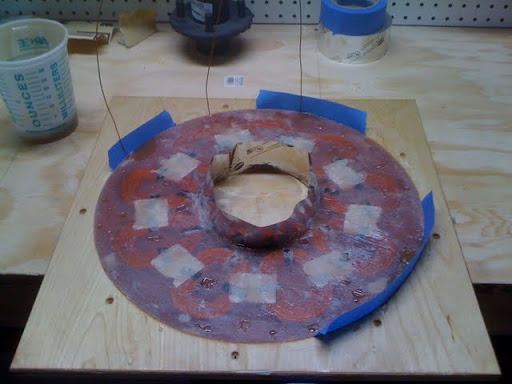
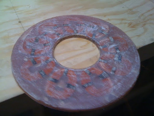
Anyway, here are a few pictures…

iphone-6-24-2009-4-44-58-pm iphone-6-24-2009-4-47-24-pm iphone-6-24-2009-4-47-35-pm iphone-6-24-2009-4-47-41-pm iphone-6-24-2009-4-48-19-pm iphone-6-24-2009-4-59-44-pm

It could have been much worse. The stator did not crack or shrink and it looks pretty good. Not bad for my first stator I think. Hopefully, it can be cleaned up and more importantly does not have any shorts in the copper. We will see. I will put all of that into the next entry because this one is getting way too long.

Building the Alternator Rotors

I found some time last week to build the rotors. This step basically involved placing the magnets on the rotor plates, banding the rotors with stainless straps, and pouring vinyl ester resin in to fill up the space between the magnets.This part was actually really easy but it was a bit nerve racking because I hadn’t worked with any type of resins before. So, I was worried that the vinyl ester resin would harden too quickly or not at all. I read a number of horror storries on www.fieldlines.com about people having big problems and it being a costly mistake. It turned out to work pretty well and so I am more confident now going into casting the stator.
iphone-6-3-2009-6-30-58-pm
Anyway, I had bought the magnets, 1/4 inch steel rotor plates, and the stainless steel rotor bands a while ago and started to assemble them last week. I heated up the bands with only a propane torch and was able to slip them over the rotor plates. The book recommends using an oxygen acetylene torch but it turns out the propane is hot enough. It was as bit tough to do this without assistance, simply because you have only a couple of seconds to slip the bands over the plates before they have cooled down and no longer fit. You have to be quick. This is really a nice way to band the rotors since you don’t have to bother welding, screwing, gluing or anything else like that. The bands are held in place very tightly simply from contracting around the circumference of the steel plates as they cool.


Well it turns out I banded the rotors before placing the magnets. That was a mistake. It was much harder to place the 12 very powerful magnets with the stainless steel bands in place because it keeps you from sliding the magnets on from the edge of the plate. It worked though with a bit of time and effort. Then I used a bit of supper glue around the edges of the magnets to temporarily hold them down. Next, I placed the 5 1/5 inch circular wooden “islands” in the center of the rotors using silicon caulk under them to create a seal. This keeps the resin from filling up the entire plate and running out the mounting holes. The book gives you a specification for these wooden peices. Make sure to put a slight inward angle all the way around the edge of the “islands” so they can easily pop out after pouring the resin. Mine broke because I had to pound them out with a hammer…not sure why. Below you can see the wooden “island”.
iphone-4-19-2009-9-19-57-am
Next I had to cast the rotor with resin. I decided to do it pretty much to the specification in the book. I used a bit less filler but the recommended amount of hardener. I poured 3/4 of a quart of vinyl ester resin into a 2 quart measuring container and then added 3 cc of hardener. Then mixed it. This is half the amount recommended by the resin manufacturer, which is what the Homebrew Wind Power guys recommend. Then I added 1/4 of a quart of ATH as filler, so I had a total of one quart of material. Then mixed it. This is the total volume that the book says you will need for one rotor. Well, it turned out to be enough resin for both rotors and then some. Not sure what the deal is with that. I’m not too surprised though since I have seen them use plastic milk jugs and just estimate how much to use. 🙂


Anyway, after a few hours the resin had not hardened at all, so I got out an electric heater put the rotors up on 2 x 4s so there was airflow under them. The temperature got up to about 110 degrees with the heater so the rotors started hardening very quickly. I turned off the heater after it started to set and let it harden slowly all night. I think they turned out really nice because there was almost no shrinkage or cracking at all. They looked almost perfect without any sanding or anything. I might put a little caulk around the inner edge of the resin since there is a little gap where the silicon caulk squirted out from underneath the wood island during casting. Check them out below…
iphone-6-3-2009-6-31-06-pm

Fieldlines Forum and Books

I have been using the www.fieldlines.com forum for asking question about building this wind turbine. The forum is run by the www.otherpower.com guys so it is very helpful and top notch advice. Anyway, I wanted to add them as links here so they are documented. I have asked a lot of questions about welding the frame and tail as well as getting started on the alternator…
Also, I have read a few other wind turbine books lately. They are all very good books if you are interested in building or just buying a wind turbine.
iphone-4-18-2009-3-02-43-pm iphone-4-18-2009-3-03-32-pm iphone-4-18-2009-3-03-57-pm

Preparing for the Alternator

Ok, it has been a while since I worked on the wind turbine because the workshop has been fragin cold!!!! I am going to need to insulate and heat the garage for sure, otherwise I won’t be able to use the shop for a couple months out of the year. Anyway, now that I am finished with the welding of the frame and tail it is time to cast the stator and rotors to make the alternator. I have spent the last weekend or two building molds, jigs, etc for building the alternator and ordering the materials I will need for these steps.
I build the coiled winder below so I can make 9 consistent looking copper coils. I used this same coil winder design at the sustainable living festival workshop and it worked great.
iphone-4-18-2009-3-26-04-pm iphone-4-18-2009-3-26-19-pm
I also build the birch plywood mold for casting the stator in. It was a bit of work but turned out good I think. It is sanded and coated with a few coats of boiled linseed oil.

iphone-4-18-2009-3-27-00-pm iphone-4-18-2009-3-27-35-pm

I also build a little template for laying out the copper coils just like they recommend in the Homebrew Wind Power book. This just helps to get the winding laid out evenly. You actually glue and solder all the coils together on this template and then move them over as one unit to the stator mold above for casting.
iphone-4-19-2009-9-18-12-am
I also ordered all the materials I will need to cast the resin parts. I ordered plenty of vinyl ester resin and a filler called ATH, which is supposed to disparate heat in the stator and lower the cost since the resin is relatively expensive. I also ordered some 1/4 inch fiberglass strand filler, which should strengthen the stator. You can see pictures of all these below. Oh yeah, I also ordered mold release wax for rubbing on the mold and some fiberglass mat for reinforcing the stator.
iphone-4-19-2009-9-37-19-am iphone-4-19-2009-9-37-36-am iphone-4-19-2009-9-38-02-am iphone-4-19-2009-9-40-55-am
I will probably do the rotor castings at the same time as the stator, but I need to figure out how I want to do them. I am not going to build the wood molds that they do in the book. I am going to either band the rotors with stainless steel or just use tape to damn up the edge of the rotors for casting like you see below. Oh yeah, I made a couple wooden islands pieces that sit in the middle of the rotors like you see below. You add a bead of caulk under the island and press it in place. This will make since when I actually do the casting.
iphone-4-19-2009-9-19-57-am


Anyway, enough for today.

Building the Tail

I finished the tail the other day. Take a look…
iphone-1-16-2009-7-58-49-pm iphone-1-18-2009-1-14-18-pm iphone-1-18-2009-1-14-33-pm iphone-1-18-2009-1-14-41-pm iphone-1-28-2009-6-11-24-pm iphone-2-16-2009-5-51-39-pm iphone-2-16-2009-5-53-52-pm

It is actually starting to look like a wind turbine now. The tail was a bit tuff to build because the welds were all at strange angles, and the tail is long enough that it is a bit unwieldy to work on. It would be best to build a couple of jigs for getting everything setup and angled correctly. This would save a lot of time. I had a little trouble finding the right pipe sized for the tail pivot. It is supposed to be 1 – 1/4 schedule 40 pipe hanging off the frame for the pivot. I found something that worked but am not sure it is shedule 40 because the walls are a bit thinner….I hope it holds up. I will work this out a bit better on the next turbine.

Anyway, this milestone means I am finished doing the welding and can move on to casting the stator (the copper windings) and rotors (plates with magnets attached). I should probably wait a bit longer for the temperature to rise into the seventies or so before doing the vinyl ester resin casting. I hear it is a bit more tricky at very low temperatures, and I want to be comfortable so I can concentrate on doing the next steps right.

Building the Frame

So the first step is to build the frame of the wind turbine. This is the part that mounts on the tower and holds the entire turbine together. It is a bit more complex then you might first think because there are three separate parts that pivot or spin: the tail pivot, yaw bearing, and the trailer spindle. In the picture below you can see the tail bearing on the left side, the yaw bearing is vertically oriented in the middle, and the trailer spindle on the right side of picture below.
iphone-9-21-2008-11-44-36-am
The primary job of the frame is to orient the entire turbine into the wind so the central shaft, called a yaw bearing, is able to rotate 360 degrees. The yaw bearing will be able to rotate because it slips over a greased bushing on the top of the tower. The tail will hang off the back and swings up and in towards the frame in higher winds. Like the yaw bearing the tail bearing is simply a greased bushing, allowing it to pivot in the wind. Finally, the trailer spindle is where the alternator and blades will be attached via a trailer hub. This all may not make a lot of sense at first, but will become clear a bit later.
All the parts that make up the alternator (copper windings, magnet rotors) and the blades will sit around the spindle. The magnet rotors and blades do the spinning because they are mounted to a 2000 lb trailer hub, which is attached to the spindle on the frame. The stator in this design is stationary and sandwiched between the 2 magnet rotors. So unlike most common AC motor or alternators, the magnets spin, not the copper winding. But, I will cover this all later in other entries.
The design requires you to weld the frame together from a bunch of flat 1/4 inch pieces of steel and schedule 40 pipe. The book outlines exactly what you need to buy and how to measure and cut each piece. You start out with basically all of the parts you see below. I found a couple shops that will cut out the 1/4″ flat parts on either a plasma cutter or water jet cutter for a fairly good price, but I had the otherpower.com guys do it because it they had the best price (and I would rather give them my money anyway).
iphone-1-16-2009-7-53-08-pm iphone-1-16-2009-7-56-57-pm
And after a bit of work with a plasma cutter and a mig welder you end up with the finished frame below. I used the plasma cutter to cope the ends of the pipes so they fit together.
iphone-1-16-2009-7-49-20-pm iphone-1-16-2009-7-49-47-pm
I built the wood jig below to set up all the pipes together at exactly the right angles, so I could easily weld the entire frame together without holding things in place. The pipes sit at strange angles so this is really necessary. The spindle points up about 7 degrees and forward a bit, so this orients everything just right.
iphone-1-16-2009-8-02-47-pm iphone-1-28-2009-6-07-04-pm iphone-1-28-2009-6-07-13-pm
Anyway it turned out pretty good and just needs a bit of clean up grinding. I plan on either painting the frame with a marine grade paint to perhaps paying someone to do an electric powder coat. I have to look at prices and see if the powder coat is affordable or not. So, next I am going to build the tail. It should go pretty quickly and then I will have all the welding done.